Modern computer numerical control (CNC) machining is a manufacturing innovation with applications across various industries. With the ability to achieve tight tolerances and exact specifications, this automated process saves manufacturers time, money and materials. A core component of the modern CNC process is computer-aided design (CAD).
In this article, we will uncover CAD’s application in CNC operations, including how it works and the benefits. We will also go over some common CAD software and file formats.
Learn About Our CNC Machining Services
CNC machines are a type of industrial equipment that uses computer software to dictate and automate the movements of a machining tool. Following the programmed paths, the tool subtracts material from a workpiece to form the desired shape.
Before the tool can begin machining, it needs a set of instructions to tell it where to move and at what speed. It receives these instructions in the form of G-code, a CNC programming language. While some CNC operators can input G-code manually into the machine, most people use computer-aided manufacturing (CAM) software.
CAM software creates the tool paths and G-code for the CNC machine, but it needs a model to work from. This is where CAD comes in. Using CAD, designers create 2D or 3D modes of the end product, which the CAM software converts into G-code. While the tool does the final and most crucial part of the machining process, CAD makes it all possible.
Learn About Our CNC Machining Services
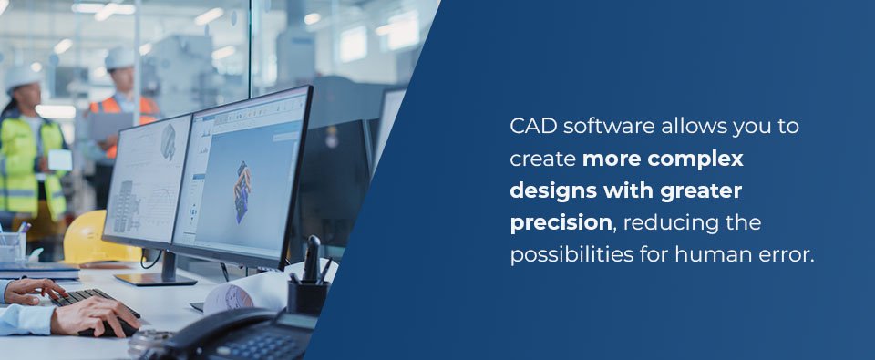
The usage of CAD in CNC processes has revolutionized CNC machining, thanks to its digital nature. Without CAD, designers would need to draw product specifications manually, which takes longer and is prone to errors. Designers can now create intricate digital representations of products in CAD software for prototyping and optimization.
Integrating CAD with CNC machining offers the following benefits:
Learn About Our CNC Machining Services
The best CAD software will meet your design requirements and integrate with your chosen CAM software. You should also consider what file formats it is compatible with, cost and ease of use. Some popular CAD software options include:
CNC machining starts with a prototype in CAD software, but how does this design end up on the CNC machine? While the process differs slightly depending on the machine, it usually follows these basic steps:
Learn About Our CNC Machining Services
With many CAD file formats available, it can be hard to determine the right one for your project. However, choosing the correct one is essential to reduce errors and frustration. CAD software file types mainly fall into two categories:
Neutral files are the most universal option for CAD users, and you can typically use them in any software. Their main advantage is interoperability, which is essential when working with a client or collaborator using different software. Some examples of neutral CAD file formats are STEP, IGES, STL and QIF.
While these files are best for compatibility, there are limitations to note. Some CAD software contains unique and advanced features. However, neutral files sometimes cannot store all the data from this software, which is needed to export them properly. When you attempt to open them in other software, the geometry of the design may be inaccurate or have errors. You will have to spend extra time fixing the design to make it work again. In some cases, the file may not open at all.
A native file is a proprietary format related to a specific CAD software. You can only use this file type exclusively for that software. For example, SOLIDWORKS software uses .sldprt and .sldasm file extensions. The software designers optimize native file types for the software and its features. This means the files hold the necessary information and work best with the related software.
Some neutral file types cannot hold all the unique information from a particular software. As such, they might not translate the file correctly, and you may end up with errors and inaccurate measurements. Use native file formats if you do not need to send the files to someone else or use them in another software.
American Micro Industries provides custom machining services and materials for foam, phenolics, and plastic CNC machining. Whether you need just the machining or the materials as well, we have got you covered. We have clients in the manufacturing, military, electrical, automotive, and medical industries, which we serve from our facilities in Chambersburg, Pennsylvania.
We pride ourselves on our customer service, competitive pricing, and fast turnaround times. No order is too small, and you can always count on us to provide the highest-quality parts for your project. Our experience and knowledge from over 20 years in business help us meet even the most complex requirements.
Contact us today to get a free quote or chat with our team!
